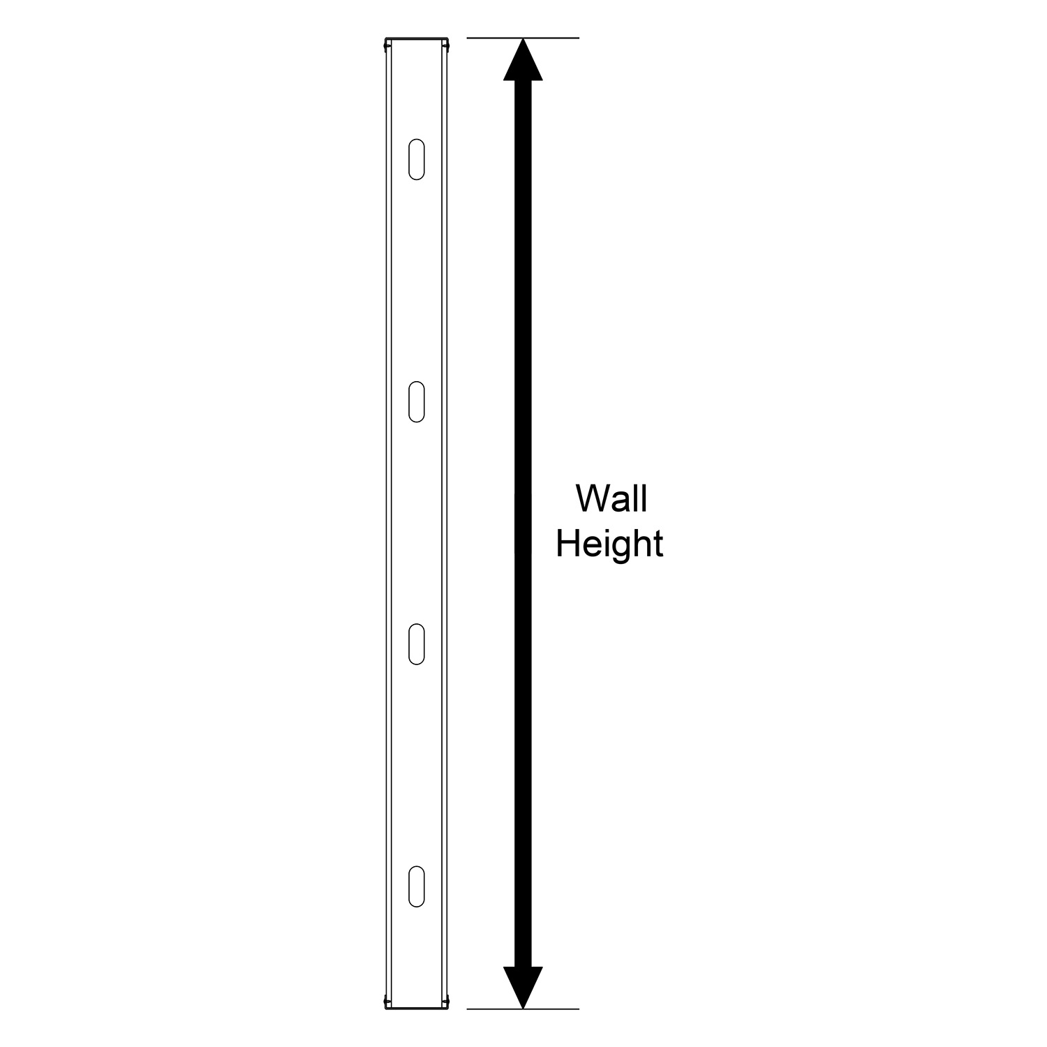
Guidance for calculating the height of the wall, or how tall the studs need to be from bottom track to top track
This is relatively simple: the height used in the stud selector is based on the actual length of the studs as they will be installed in the building. Except for ledger framing, this is typically slightly less than the floor-to-floor height since some space is taken up by the bearing of the slab or joist on the wall.
StudSelector has pre-listed wall heights every 4 inches: e.g. 11’-0”, 11’-4”, 11’-8”, 12’-0”, etc. If the actual stud height you are checking falls between two of these values, use the next-highest stud length for your capacity check. For example, if a stud is 12’-6” tall, use the next-highest value in the selector, which is 12’-8”. This will give slightly conservative values compared to the actual 12’-6” wall height.
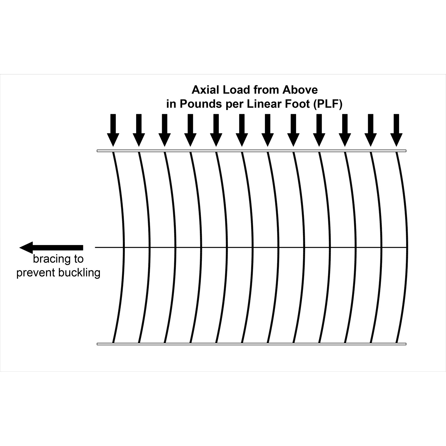
Guidance for calculating axial loads or the weight in pounds per lineal foot (PLF) on top of the wall
The axial load on a wall is the total of all of the gravity loads coming down from above. For a mezzanine, these will be floor loads, for 1-story buildings, these will be roof loads, and for multi-story buildings, these will include both floor and roof loads. In chapter 16 of the International Building Code (IBC), there are details on different load types, and requirements for load combinations and load factors.
The StudSelector does not differentiate for different load types: it assumes the user has already combined loads using allowable strength design (ASD) load combinations and has come up with a single total worst-case (maximum) load to be applied to the wall. The tables assume that the load is equally distributed to all studs in the wall and that loads are applied at the centroid of the stud. Because these assumptions can be unconservative when load distribution members (LDMs) or ledger framing is used, the stud selector output must be evaluated by a competent structural engineer who is well-versed in CFS load-bearing structural design. To account for unequal load distribution or other loading issues, an axial load reduction factor should be considered.
Guidance for calculating the pressure pushing against the face of the wall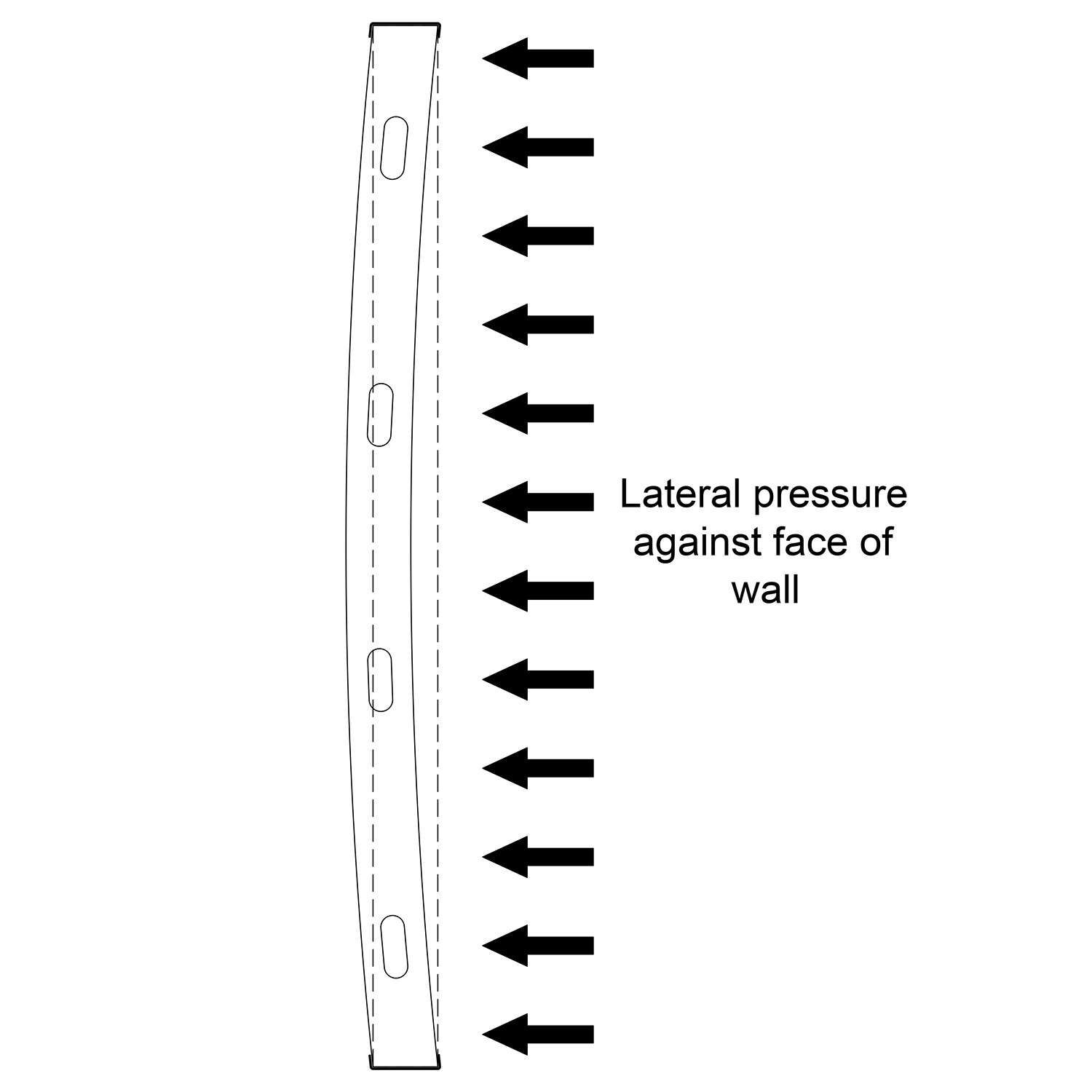
There are two types of pressures used in StudSelector data:
- An interior live load pressure of 5 PSF. This unreduced pressure is a uniform value required for all interior partitions greater than 6’ tall, in accordance with IBC section 1607.14.
- Wind load. This is a lateral pressure on building exterior walls, calculated based on several factors, including wind speed, building height, building use, terrain, and structure shape. Unfortunately, there is not a direct conversion from wind speed to wind pressure.
For non-engineers wanting to use StudSelector for estimating purposes only:
- Use 5 PSF for interior partitions.
- Use 30 PSF for exterior walls exposed to wind. This will be conservative for most areas of the country away from hurricane oceanline for mid-rise and low-rise buildings.
- Use 40 to 50 PSF for mid-rise buildings along the Atlantic and Gulf coasts.
The 5 PSF live load has not been reduced for deflection.
For engineers using building codes to calculate 10 PSF and higher wind pressure:
IBC 2021/ASCE 7-16: Because of changes in building codes, wind pressures determined using codes that reference ASCE 7-10 or ASCE 7-16 are strength level loads (LRFD) in comparison to those determined in earlier IBC codes which were service level loads (ASD). The load/span data in StudSelector are based on service level (ASD) wind loads. Therefore, to properly use StudSelector, multiply the IBC (2012 - 2021) design wind pressures by 0.6 (Reference section 2.4 ASCE 7-16) prior to entering the load/span tables.
Example:
- ASCE 7-16 Calculated Design Wind Pressure = 25 PSF (Strength level loads, LRFD)
- Convert to service level loads (ASD) = 25 PSF x 0.6 = 15 PSF
- Use 15 PSF as the pressure value used in this table to determine the member capacity.
For codes that use ASD wind speeds: StudSelector values are based on service level (ASD) wind speeds. Therefore, the pressures calculated using ASD wind speeds do not need to be modified prior to using the StudSelector.
Guidance for calculating how much Deflection is permitted in the wall
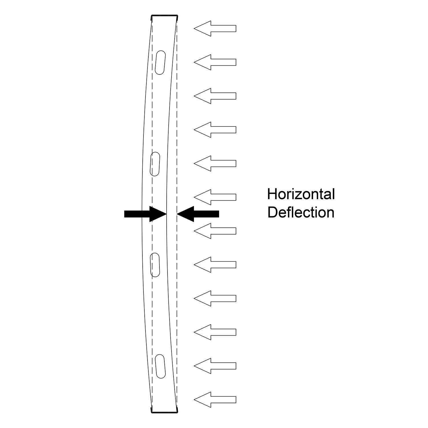 The bending of a wall stud under full lateral pressure is typically governed by the type of finish materials used on the wall. Brittle cladding like brick veneer or tile cannot handle as much deflection as more flexible materials, such as exterior insulation and finish system (EIFS) or vinyl siding. The table below gives some common cladding materials and the suggested permitted deflection. The deflection of any product must be checked with the manufacturer to conform to the product warranties.
Note that the deflection of any product must be checked with the manufacturer to conform to the product warranties. Additionally, the deflection limits are given as a fraction of the overall height of the wall, represented by the letter “L”. For example, for a brick veneer wall that is 10’-0” tall, deflection should not exceed one six-hundredth of the span. So the deflection limit, L/600, is 10’/600, which is 0.200 inches.
|
Deflection |
Material |
Maximum deflection permitted in 12’ span |
||
|
L/720 |
Specialty tile or stone |
0.200” |
3/16” |
5.08 mm |
|
L/600 |
Brick Veneer, stone |
0.240” |
¼” |
6.10 mm |
|
L/480 |
Some floor systems |
0.300” |
5/16” |
7.62 mm |
|
L/360 |
Stucco, Tile |
0.400” |
3/8” |
10.16 mm |
|
L/240 |
EIFS, GFRC |
0.600” |
5/8” |
15.24 mm |
|
L/180 |
Composite panels |
0.800” |
13/16” |
20.32 mm |
|
L/120 |
Gypsum board |
1.200” |
1-3/16” |
30.48 mm |
GFRC = Glass fiber reinforced gypsum; EIFS = exterior insulation and finish system. This table provides a few examples: please check with cladding manufacturer for specific deflection requirements.
Values from the StudSelector can be specified to meet a specific deflection criterion ranging from L/120 to a very restrictive L/720 Code requirements for deflection are listed in table 1604.3 of the IBC, requiring L/360 for walls with plaster or stucco finishes, L/240 for other brittle finishes, and L/120 for flexible finishes. Footnote F from this table allows reduced wind load to be used when calculating deflection. This wind load reduction has been incorporated into StudSelector for pressures of 10 PSF and greater, but has not been used for 5 PSF interior partitions, since this is a live load and not a wind load.
 Guidance on the depth of the stud
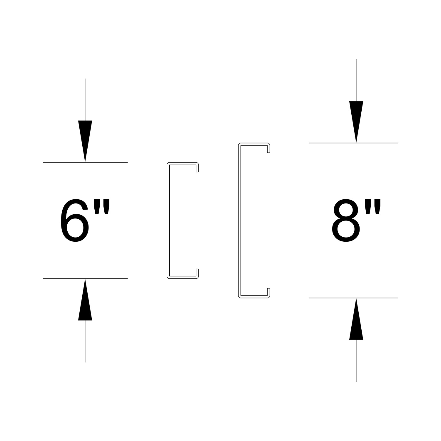
For most multi-story load-bearing wall applications, the stud cavity is typically 6 inches. However, for some taller walls with high axial loads, it may be more economical going with 8” deep studs. The StudSelector will choose the most efficient system using eight (8"), six (6"), or four-inch(4") studs. Note that for tight deflection criteria, such as with brick or stone veneer, the deeper studs typically provide a more efficient option. Additionally, note that although some load-bearing structures use 3-5/8” or 4” bearing walls, those options are not currently available in StudSelector.
